Raspberry Pi Kubernetes Cluster Case: A Hot-Swappable Personal Cloud Enclosure
Quite a few months ago, I started an ambitious hardware project: I wanted to build a compact case for several Raspberry Pi boards and use them as a small Kubernetes cluster.
The main constraints were:
- The case should host three Raspberry Pi boards.
- Each board should be hot-swappable.
- The system should stay quiet under normal load.
Here is the result:

Case
I liked the idea of cutting cases from acrylic glass, so I designed the enclosure to be made entirely from inexpensive 3 mm and 4 mm acrylic sheets — the kind of material that is easy to find in a DIY shop.
Of course, cutting the parts requires access to a 30–40 W laser cutter. I was lucky enough to find one at Marineholmen Makerspace (now changed to Bergen Fellesverksted).
I also wanted the Raspberry Pi boards to be hot-swappable, which meant I needed a way to install and remove any individual board without disturbing the others. The solution was to design a separate frame for each Raspberry Pi and add grooves to the case. Each board, mounted on its own frame, can be pushed into the enclosure and pulled out when needed.
Here is a 3D model of a Raspberry Pi with a PoE module and the two frame parts:

The case itself is assembled from the following parts:
- Left, right, top, and bottom outer panels.
- Top and bottom internal panels with grooves for the Raspberry Pi frames.
- A back panel with a fan grille.
- A front panel with openings for USB and Ethernet ports.
The back panel with the fan grille can be removed without disassembling the whole enclosure. This makes it much easier to access the fan controller and service the cooling system.

Power
It is hard to overestimate the importance of a good power supply for Raspberry Pi boards, especially when running several of them in a cluster.
After trying different solutions, I settled on the RT5400-5V Power over Ethernet module. This module provides 4 A of stabilized 5 V power, costs around $7, and is completely silent. I only had to add several electrolytic capacitors and design a PCB to connect it to the Raspberry Pi’s I/O and PoE pins.

The PoE module does not block airflow over the central part of the Raspberry Pi board. Instead, it extends over the top edge of the board. Since the RT5400 module is installed perpendicular to the PoE PCB, it also does not take much space inside the enclosure.
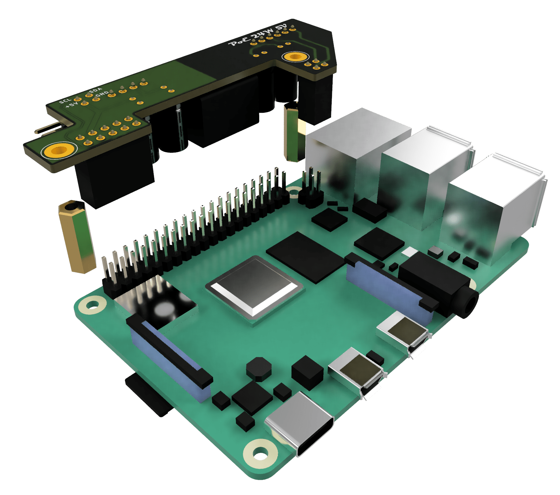
In addition to supplying power, each PoE PCB has an extra connector that exposes 5 V and the I2C bus. This connector is used to power and control the chassis fan.
When a Raspberry Pi board is pushed into the case, the connector slides into a socket on a special rail PCB. The rail PCB is connected to the fan controller on the left side of the enclosure.

Cooling
I decided to use the largest fan I could fit into the case. A larger fan can move the same amount of air at a lower speed, and a slower fan usually means less noise.
I picked a Noctua NF-A8 PWM fan. It is an 80 × 80 × 25 mm fan with PWM support and very low noise.
Since each Raspberry Pi is powered individually through PoE, I needed a fan power circuit that would work regardless of which Raspberry Pi boards were installed. The fan should receive power as long as at least one board is present.
To solve this, I used low-drop Schottky diodes in an OR-ing circuit. This allows any available power source to supply the fan without the risk of reverse current flowing back into another board.
Although 80 × 80 mm 5 V fans with PWM support are available, I decided to use the 12 V version because it is more widely available. For the 5 V to 12 V conversion, I chose the MIC2288YD5 step-up converter.
Here is the schematic:

To control the PWM fan from the Raspberry Pi boards — and eventually from a service running inside the Kubernetes cluster — I needed an I2C fan controller. I chose the EMC2101 from Microchip/SMSC.
This IC can control a 4-pin fan and monitor its speed through the I2C bus, which is supported by Raspberry Pi boards.
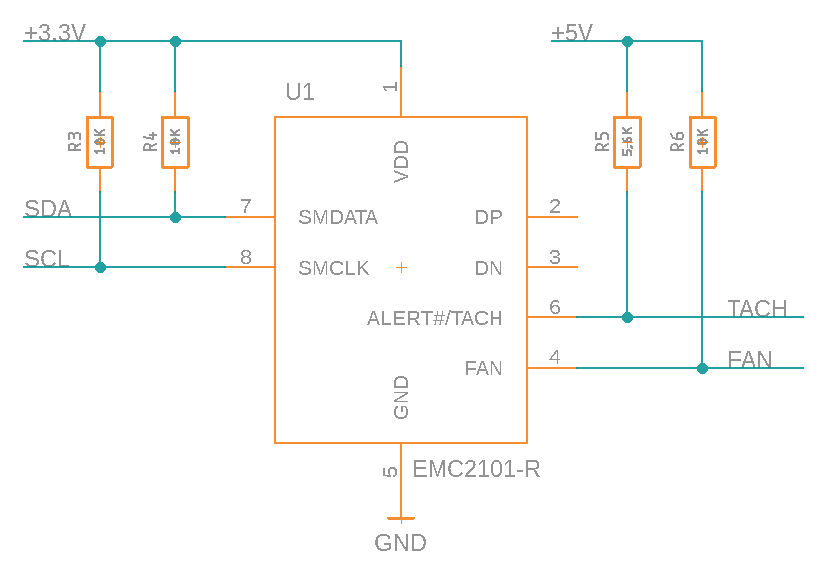
One important detail is that the EMC2101 comes in two variants: EMC2101 and EMC2101-R. Only the EMC2101-R variant can be configured to start with a 100% duty cycle using a 5.6 kΩ pull-up resistor connected to 5 V and TACH.
Documentation
The project documentation includes:
- Frame panels: drawings and laser-cutting templates.
- Case panels: drawings and laser-cutting templates.
- PoE assembly: schematics, EagleCAD PCB files, and BOM.
- Power and I2C rail: schematics, EagleCAD PCB files, and BOM.
- Fan controller: schematics, EagleCAD PCB files, and BOM.
Complete documentation, design files, schematics, PCB layouts, and bills of materials are available on GitHub.


 RSS - Posts
Great recourse, Thank you!